Monday, June 11, 2018

laser ignition system

Abstract

Economic as well as environmental constraints demand a further reduction in the fuelconsumption and the exhaust emissions of motor vehicles. At the moment, directInjected fuel engines show the highest potential in reducing fuel consumption and exhaust emissions. Unfortunately, conventional spark plug ignition shows a major disadvantage with modern spray-guided combustion processes since the ignition location cannot be chosen optimally.
It is important that the spark plug electrodes are not hit by the injected fuel because otherwise severe damage will occur.Additionally, the spark plug electrodes can influence the gas flow inside the combustion chamber. It is well know that short and intensive laser pulses are able to produce an ”optical breakdown” in air. Necessary intensities are in the range between 1010- 1011W/cm2.1, 2 at such intensities, gas molecules are dissociated and ionized Within the vicinity of the focal spot of a laser beam and a hot plasma is generated. ThisPlasma is heated by the incoming laser beam and a strong shock wave occurs. The expanding hot plasma can be used for the ignition of fuel-gas mixtures.

Drawbacks Of Conventional Spark Ignition

Location of spark plug is not flexible as it require shielding of plug from immense heat and fuel spray.
It is not possible to ignite inside the fuel spray.
It require frequent maintenance to remove carbon deposits..
Leaner mixtures cannot be burned.
Degradation of electrodes at high pressure and temperature.
Flame propagation is slow.
Multi point fuel ignition is not feasible.
Higher turbulence levels are required.

What Is Laser?

Lasers provide intense and unidirectional beam of light. Laser light is monochromatic (onespecific wavelength). Wavelength of light is determined by amount of energy releasedwhen electron drops to lower orbit. Light is coherent; all the photons have same wavefronts that launch to unison. Laser light has tight beam and is strong and concentrated.
Tomake these three properties occur takes something called “Stimulated Emission”, inwhich photon emission is organized. Main parts of laser are power supply, lasing medium and a pair of precisely aligned mirrors. One has totally reflective surface and other is partially reflective (96 %). The most important part of laser apparatus is laser crystal. Most commonly used laser crystalis manmade ruby consisting of aluminum oxide and 0.05% chromium. Crystal rods are round and end surfaces are made reflective.
A laser rod for 3 J is 6 mm in diameter and70 mm in length approximately. Laser rod is excited by xenon filled lamp, whichsurrounds it. Both are enclosed in highly reflective cylinder, which directs light fromflash lamp in to the rod. Chromium atoms are excited to higher energy levels. The excitedions meet photons when they return to normal state. Thus very high energy is obtained inshort pulses. Ruby rod becomes less efficient at higher temperatures, so it is continuouslycooled with water, air or liquid nitrogen. The Ruby rod is the lasing medium and flashtube pumps it.
Laser Ignition System
Ruby Laser
Ruby Laser

Laser Induced Spark Ignition

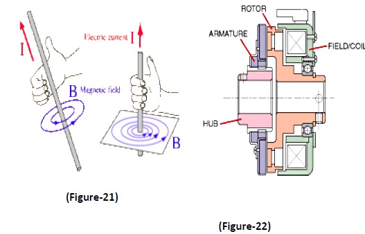
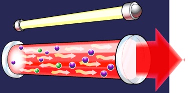
The process begins with multi-photon ionization of few gas molecules which releaseselectrons that readily absorb more photons via the inverse bremsstrahlung process toincrease their kinetic energy. Electrons liberated by this means collide with othermolecules and ionize them, leading to an electron avalanche, and breakdown of the gas.Multiphoton absorption processes are usually essential for the initial stage of breakdownbecause the available photon energy at visible and near IR wavelengths is much smaller than the ionization energy.
For very short pulse duration (few picoseconds) themultiphoton processes alone must provide breakdown, since there is insufficient time forelectron-molecule collision to occur. Thus this avalanche of electrons and resultant ionscollide with each other producing immense heat hence creating plasma which issufficiently strong to ignite the fuel. The wavelength of laser depend upon the absorptionproperties of the laser and the minimum energy required depends upon the number ofphotons required for producing the electron avalanche.
Laser Induced Spark Ignition
The minimum ignition energy required for laser ignition is more than that for electric spark ignition because of following reasons: An initial comparison is useful for establishing the model requirements, and for identifying causes of the higher laser MIE. First, the volume of a typical electrical ignition spark is 10^-3 cm3. The focal volume for a typical laser spark is 10^-5 cm3. Since atmospheric air contains _1000 charged particles/cm3, the probability of finding a charged particle in the discharge volume is very low for a laser spark. Second, an electrical discharge is part of an external circuit that controls the power input, which may last milliseconds, although high power input to ignition sparks isusually designed to last <100 ns.
Breakdown and heating of laser sparks depend only onthe gas, optical, and laser parameters, while the energy balance of spark dischargesdepends on the circuit, gas, and electrode characteristics. The efficiency of energytransfer to near-threshold laser sparks is substantially lower than to electrical sparks, somore power is required to heat laser sparks. Another reason is that, energy in the form of photons is wasted before the beam reach the focal point. Hence heating and ionizing the charge present in the path of laserbeam. This can also be seen from the propagation of flame which propagates longitudinally along the laser beam. Hence this loss of photons is another reason forhigher minimum energy required for laser ignition than that for electric spark.

Advantages

 Location of spark plug is flexible as it does not require shielding from immense heat and fuel spray and focal point can be made any where in thecombustion chamber from any point It is possible to ignite inside the fuel spray asthere is no physical component at ignition location.
 It does not require maintenance to remove carbon deposits because of itsself cleaning property.
 Leaner mixtures can be burned as fuel ignition inside combustion chamberis also possible here certainty of fuel presence is very high.
 High pressure and temperature does not affect the performance allowing the use of high compression ratios.
 Flame propagation is fast as multipoint fuel ignition is also possible.
 Higher turbulence levels are not required due to above said advantages

electromagnetic clutch system

Abstract

A clutch is a mechanism for transmitting rotation, which can be engaged and disengaged. Clutches are useful in devices that have two rotating shafts. In these devices, one shaft is typically driven by motor or pulley, and other shaft drives another device. The clutch connects the two shafts so that they can either be locked together and spin at the same speed (engaged), or be decoupled and spin at different speeds (disengaged).
The clutch disc (centre) spins with the flywheel (left). To disengage, the lever is pulled (black arrow), causing a white pressure plate (right) to disengage the green clutch disc from turning the drive shaft, which turns within the thrust-bearing ring of the lever. Never will all 3 rings connect, with any gaps.

Electromagnetic Clutch

Electromagnetic clutches operate electrically, but transmit torque mechanically. This is why they used to be referred to as electro-mechanical clutches.

CONSTRUCTION

A horseshoe magnet has a north and south pole. If a piece of carbon steel contacts both poles, a magnetic circuit is created. In an electromagnetic clutch, the north and south pole is created by a coil shell and a wound coil. In a clutch, when power is applied, a magnetic field is created in the coil. This field (flux) overcomes an air gap between the clutch rotor and the armature. This magnetic attraction, pulls the armature in contact with the rotor face. The frictional contact, which is being controlled by the strength of the magnetic field, is what causes the rotational motion to start.
The torque comes from the magnetic attraction, of the coil and the friction between the steel of the armature and the steel of the clutch rotor. For many industrial clutches, friction material is used between the poles. The material is mainly used to help decrease the wear rate, but different types of material can also be used to change the coefficient of friction (torque for special applications). For example, if the clutch is required to have an extended time to speed or slip time, a low coefficient friction material can be used and if a clutch is required to have a slightly higher torque (mostly for low rpm applications), a high coefficient friction material can be used.
In a clutch, the electromagnetic lines of flux have to pass into the rotor, and in turn, attract and pull the armature in contact with it to complete clutch engagement. Most industrial clutches use what is called a single flux, two pole design. Mobile clutches of other specialty electromagnetic clutches can use a double or triple flux rotor. The double or trip flux refers to the number of north/south flux paths, in the rotor and armature.
Electromagnetic Clutch
This means that, if the armature is designed properly and has similar banana slots, what occurs is a leaping of the flux path, which goes north south, north south. By having more points of contact, the torque can be greatly increased. In theory, if there were 2 sets of poles at the same diameter, the torque would double in a clutch. Obviously, that is not possible to do, so the points of contact have to be at a smaller inner diameter. Also, there are magnetic flux losses because of the bridges between the banana slots. But by using a double flux design, a 30%-50% increase in torque, can be achieved, and by using a triple flux design, a 40%-90% in torque can be achieved. This is important in applications where size and weight are critical, such as automotive requirements.
The coil shell is made with carbon steel that has a combination of good strength and good magnetic properties. Copper (sometimes aluminium) magnet wire, is used to create the coil, which is held in shell either by a bobbin or by some type of epoxy/adhesive.
To help increase life in applications, friction material is used between the poles on the face of the rotor. This friction material is flush with the steel on the rotor, since if the friction material was not flush, good magnetic traction could not occur between the faces. Some people look at electromagnetic clutches and mistakenly assume that, since the friction material is flush with the steel that the clutch has already worn down but this is not the case. Clutches used in most mobile applications, (automotive, agriculture, construction equipment) do not use friction material. Their cycle requirements tend to be lower than industrial clutches, and their cost is more sensitive. Also, many mobile clutches are exposed to outside elements, so by not having friction material, it eliminates the possibility of swelling (reduced torque), that can happen when friction material absorbs moisture.

How Does It Works

The clutch has four main parts: field, rotor, armature, and hub (output) . When voltage is applied the stationary magnetic field generates the lines of flux that pass into the rotor. (The rotor is normally connected to the part that is always moving in the machine.) The flux (magnetic attraction) pulls the armature in contact with the rotor (the armature is connected to the component that requires the acceleration), as the armature and the output start to accelerate. Slipping between the rotor face and the armature face continues until the input and output speed is the same (100% lockup). The actual time for this is quite short, between 1/200th of a second and 1 second.
Disengagement is very simple. Once the field starts to degrade, flux falls rapidly and the armature separates. One or more springs hold the armature away from the rotor at a predetermined air gap.

Basic operation of electromagnetic clutch

• The clutch has four main parts: field, rotor, armature, and hub (output) (Figure-22). When voltage is applied the stationary magnetic field generates the lines of flux that pass into the rotor. (The rotor is normally connected to the part that is always moving in the machine.) The flux (magnetic attraction) pulls the armature in contact with the rotor (the armature is connected to the component that requires the acceleration), as the armature and the output start to accelerate. Slipping between the rotor face and the armature face continues until the input and output speed is the same (100% lockup). The actual time for this is quite short, between 1/200th of a second and 1 second.
Electromagnetic Clutch
• Disengagement is very simple. Once the field starts to degrade, flux falls rapidly and the armature separates. One or more springs hold the armature away from the rotor at a predetermined air gap.
• Voltage/current - and the magnetic field
• If a piece of copper wire was wound, around the nail and then connected to a battery, it would create an electro magnet. The magnetic field that is generated in the wire, from the current, is known as the “right hand thumb rule”. (FIGURE-21) The strength of the magnetic field can be changed by changing both wire size and the amount of wire (turns). EM clutches are similar; they use a copper wire coil (sometimes aluminum) to create a magnetic field.
• The fields of EM clutch can be made to operate at almost any DC voltage, and the torque produced by the clutch or brake will be the same, as long as the correct operating voltage and current is used with the correct clutch. If a 90 V clutch, a 48 V clutch and a 24 V clutch, all being powered with their respective voltages and current, all would produce the same amount of torque. However, if a 90 V clutch had 48 V applied to it, this would get about half of the correct torque output of that clutch. This is because voltage/current is almost linear to torque in DC electromagnetic clutches.
• A constant power supply is ideal if accurate or maximum torque is required from a clutch. If a non regulated power supply is used, the magnetic flux will degrade, as the resistance of the coil goes up. Basically, the hotter the coil gets the lower the torque will be, by about an average of 8% for every 20°C. If the temperature is fairly constant, but there may not be enough service factor in your design for minor temperature fluctuation. Over-sizing, the clutch would compensate for minor flux. This will allow the use a rectified power supply which is far less expensive than a constant current supply.
• Based on V = I × R, as resistance increases available current falls. An increase in resistance, often results from rising temperature as the coil heats up, according to: Rf = Ri × [1 + αCu × (Tf - Ti)] Where Rf = final resistance, Ri = initial resistance, αCu = copper wire’s temperature coefficient of resistance, 0.0039 °C-1, Tf = final temperature, and Ti = initial temperature.

Engagement time

There are actually two engagement times to consider in an electromagnetic clutch. The first one is the time that it takes for a coil to develop a magnetic field, strong enough to pull in an armature. Within this, there are two factors to consider. The first one is the amount of ampere turns in a coil, which will determine the strength of a magnetic field. The second one is air gap, which is the space between the armature and the rotor. Magnetic lines of flux diminish quickly in the air.. Air gap is an important consideration especially with a fixed armature design because as the unit wears over many cycles of engagement the armature and the rotor will create a larger air gap which will change the engagement time of the clutch. In high cycle applications, where registration is important, even the difference of 10 to 15 milliseconds can make a difference, in registration of a machine. Even in a normal cycle application, this is important because a new machine that has accurate timing can eventually see a “drift” in its accuracy as the machine gets older.
The second factor in figuring out response time of a clutch is actually much more important than the magnet wire or the air gap. It involves calculating the amount of inertia that the clutch needs to accelerate. This is referred to as “time to speed”. In reality, this is what the end-user is most concerned with. Once it is known how much inertia is present for the clutch to start then the torque can be calculated and the appropriate size of clutch can be chosen.
Most CAD systems can automatically calculate component inertia, but the key to sizing a clutch is calculating how much inertial is reflected back to the clutch or brake. To do this, engineers use the formula: T = (wk2 × ΔN) / (308 × t) Where T = required torque in lb-ft, WK2 = total inertia in lb-ft2, ΔN = change in the rotational speed in rpm, and t = time during which the acceleration or deceleration must take place.
There are also online sites that can help confirm how much torque is required to accelerate a given amount of inertia over a specific time.

CONCLUSION

Having designed and constructed the circuit it was felt that it met all of the given specifications although there were still a number of improvements that could have been made. These improvements have been covered briefly in the discussion section and given more time they could have been implemented in the circuit. As already mentioned the only specifications not met were that on start-up the machine should rotate for 3 seconds in one direction before braking and reversing. Using the clutch method mentioned in the discussions could solve this but the design brief given did not extend to cover the drum so has not been included in the final design.
During the course of the project a number of other points became evident which greatly ease the process of designing an electronic circuit. Simulation using a computer package such as Pspice saves a considerable amount of time by allowing the circuit to be easily laid out and tested. Any changes required can be made easily without disturbing the rest of the circuit. Another advantage of Pspice is the ability to produce graphs of the outputs from the circuit, which can then be scaled, formatted and printed as required. To do this for the actual circuit requires very specialised and expensive equipment.
In conclusion, the group felt that all objectives had been met and that the final circuit was successful in fulfilling its role. A number of important lessons were learned about the problems involved in designing a circuit to meet a real-world need and ways of overcoming these problems were found.

Sunday, June 3, 2018

Forging process

Forging process is perhaps the oldest metal working process and was known even during prehistoric days when metallic tools were made by heating and hammering.
Forging is basically involves plastic deformation of material between two dies to achieve desired configuration. Depending upon complexity of the part forging is carried out as open die forging and closed die forging.
In open die forging process, the metal is compressed by repeated blows by a mechanical hammer and shape is manipulated manually.
                                                  
In closed die forging, the desired configuration is obtained by squeezing the workpiece between two shaped between two shaped and closed dies.


In forging process the forces are applied on the raw material such that the stresses induced are greater than yield and less than ultimate so that material is experiencing plastic (or) permanent deformation to get required shape. But in forging operation force applied can be either continuous or intermittent impact loads.


Types of forging methods:


1 Based on the method of force application
1.      Hand forging (Drop hammer type)
2.      Machine forging (Mechanical or hydrostatic forging)

1.1 Hand forging:

Hand forging always uses drop hammer type. Because the continuous force by the human hand, it is not sufficient to produce the deformation in work piece.

1.2 Machine forging:

In machine forging because the required force is obtained from machine it is possible to use either continuous force application or intermittent impact load application.

2. Based on method of shape obtained
1.      Open die forging
2.      Closed die forging
3.      Semi die forging

2.1 Open die forging

§  In open die forging operation only drop hammer type of force application will be used.
§  Press forging is not used since there is no time fr changing the position of component.
Features of open die die forging:
§  Repeated impact blows are given on the work.
§  Less dimensional accuracy.
§  Suitable only for simple shapes of work.
§  Requires more skill of the operator.
§  Usually used for a work before subjecting it to closed die forging (to give approximate shape.
§  Dies are simple and less expensive.
§  It can be analyzed much easily.
§  it is the simplest of all forging operations.

2.2 Closed die forging

§  Closed die forging is also called as impression die forging because the shape of the dies is impressed on the component.
§  In this the type of forging force application may be either press forging type or drop hammer type will be used.
Features of closed die forging:
§  Closed die forging involves two or more steps:
1.      Blocking die: Work is rough forged, closed to final shape.
2.      Finishing die: Work is forged to final shape and dimension.
§  Both blocking die and finishing die are machined into the same die block.
§  More number of dies are required depending on the complexity of the job.
§  Two die halves close-in & work is deformed under high pressure.
§  High dimensional accuracy/close control on tolerances.
§  Suitable for complex shapes.
§  Dies are complex and more expensive.
§  Large production rates are necessary to justify high costs.

2.3 Semi closed die forging operation

§  Only drop hammer type of force application is possible.
§  In case of open die and closed die forging operations the volume of raw material required is remaining same as that of the volume of final finished component. But in case of closed die forging operation the volume of the raw material is about 10% to 20% more than final component to be obtained.
§  To accommodate the excess volume of material it is required to provide some open space dies also called gutter.
§  Because of provision of gutter the flash is produces in the forged component.
§  This flash is unwanted material which has to be removed by trimming operation.
§  Flash and gutter is used only in case of closed die operation but not in open die or semi closed die forging operation.


Advantages of forging:

Some common advantages of choosing forging operation are listed below:
1.      Forged parts possess high ductility and offers great resistance to impact and fatigue loads.
2.      Forging refines the structure of the metal.
3.      It results in considerable saving in time, labor and material as compared to the production process of similar item by cutting from a solid workpiece and then shaping it.
4.      Forging distorts the previously created unidirectional fiber as created by rolling and increases the strength by setting the direction of grains.
5.      The forged parts can be welded easily.
6.      Because of intense working, flaws are rarely found, so have high reliability.
7.      High accuracy may be obtained in forging operation.


Disadvantages of forging:

Few disadvantages of choosing forging operation are listed below:
1.      Rapid oxidation in forging of metal surface at high temperature results in scaling which wears the dies.
2.      It is difficult to maintain close tolerances in forging operations.
3.      Forging is limited to simple shapes and has limitation for parts having undercuts etc.
4.      Some materials are not readily worked by forging.
5.      The initial cost of forging dies and the cost of their maintenance is high.
6.      The metals gets cracked or distorted if worked below a specified temperature limit.
7.      The maintenance cost of forging dies is also very high.


Safety Precautions in Forging Shop
Some safety precautions in forging shop to followed while performing forging operation to avoid injuries and accidents are listed below:

1.      Always avoid the use of damaged hammers.
2.      Never try to strike a hardened surface with a hardened tool.
3.      No person should stand in line with the flying objects.
4.      Always use the proper tongs tool to grip and lift objects according to the type of work.
5.      The anvil should always be clean and free from moisture and grease while in use.
6.      Always wear proper clothes such as apron, foot-wears and goggles.
7.      The handle of the hammer should always be tightly fitted in the head of the hammer.
8.      Always put out the fire in the forge before leaving the forging shop.
9.      Always keep the working space clean and tidy.
10.  Proper safety guards should be provided on all revolving parts.
11.  Head of the chisel should be free from burrs and should never be allowed to spread.
12.  During machine forging, always observe the safety rules prescribed for each machine.
13.  One must have the thorough knowledge and working of the forging machine before going to operate it.

2 stroke vs 4 stroke


  • In the 2 stroke engine it consists of one cycle with one rotation
  • In the 4 stroke engine it consists of one cycle with two rotations.
  • The inlet and the exhaust valves of the 4 stroke engine are replaced by 3 ports in a 2 stroke engine.
  • In 2 stroke engine the lubrication oil must be mixed with the petrol
  • In case of 4 stroke engine the lubrication and the fueling must take place separately
  • In the 2 stroke engine due to the presence of the lubrication oil, some of the lubrication oil must be combusted during the time of heat addition. Hence there is more friction and loss of work in 2 Engine
  • The power available in the 2 stroke engine is only 70% of the calculated power
  • In 4 stroke engine the power available is 90% of the calculated power
  • In 2 stroke engine the transfer port and the exhaust port are opened at the same time. Hence some fresh air fuel mixture will be escaped out of the engine cylinder, due to which there is loss of fuel.
  • For single cylinder engine the size of the flywheel is bigger than the 4 stroke engine.
  • Due to the above reason the 2 stroke engine on the roads are replaced by the 4 stroke engine
  • The overall efficiency of a 4 stroke engine is much higher than that of a 2 stroke engine.